Design Hardware with Coroutines
Post Metadata
Hardware is typically designed using a hardware description language (HDL) like Verilog (see Gus’s blog post to learn about that!). Verilog has many well-documented problems, but another thing it does not offer is much abstraction. On the one hand, there is a reasonable argument that abstractions often are not free and low-level control is a high priority for hardware designers; every hardware designer is a performance engineer. A goal of my research is figuring out how to offer hardware designers additional zero-cost abstraction mechanisms to improve their productivity and this blog post is about one of the ways I have been thinking about doing that. I recently published an article with my collaborators at the LATTE workshop at ASPLOS about implementing cache-coherence protocols using coroutines. This blog post discusses why coroutines are a good choice for implementing hardware protocols, and in particular finite-state machines, without sacrificing control.
Finite-State Machines
Many hardware modules explicitly implement finite-state machines (FSMs). These FSMs arbitrate access to shared resources, express low-level communication protocols, or sequence steps of a communication into smaller pieces achievable in a single clock cycle. FSMs are a popular abstraction mechanism because it allows the designer to encapsulate what must be done in a step versus what can remain in a default state. Hardware, unlike software, always “takes a step” so the designer must think about how every piece of state in the module should be updated instead of the state affected by single operations (or lines of software code). FSMs allow the designer to modularly reason about these state updates based on the higher level state that the computation is currently performing.
As an example of a low-level communication protocol, consider the following FSM that is handling the read request logic of a single request in a cache controller implementing the MSI coherence protocol. In short, this is a piece of hardware that is responsible for maintaining the coherence of a private L1 cache on a single processor that is sharing data with other processors and the rest of the memory system.
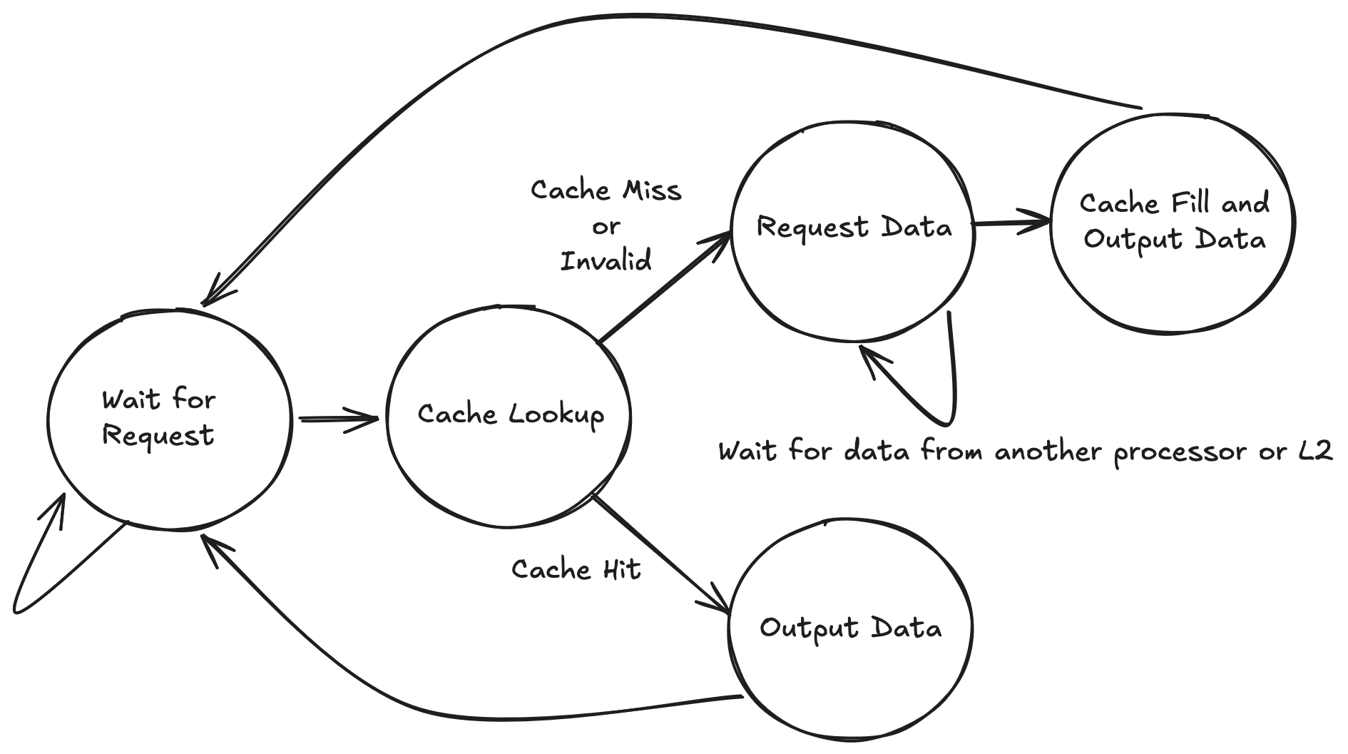
Each state represents stages of the computation and each clock cycle, exactly one transition is made (though it may be a self transition based on the state that the computation is in). This FSM starts spinning in the “Wait for Request” state. Upon receiving a request it performs a cache lookup and then based on the result (hit or miss) proceeds down one of two paths. In the hit case it immediately outputs the data. In the case of a miss, it must request the data from other processors (or the higher level caches in the memory system) and wait for it to come back. Eventually it receives the data and returns it to the processor. Note that while there is a lot going on with the diagram, there are basically only two complete computation paths through the diagram and they are relatively sequential. We shall see in the next section how that detail is obfuscated by a “general purpose” style implementation in a language like Verilog.
What’s wrong with Verilog
In Verilog or SystemVerilog, one would typically express this FSM as follows:
\\ inputs omitted above

typedef enum logic [2:0] {
    WAITING = 3'd0,
    LOOKUP = 3'd1,
    REQUEST_DATA = 3'd2,
    CACHE_FILL = 3'd3,
    OUTPUT_DATA = 3'd4
} state_t;

state_t state, next_state;

always_ff @(posedge clk or posedge reset) begin
    if (reset)
        state <= WAITING
    else
        state <= next_state
end

// actual cache processing logic omitted
always_comb begin
    next_state = state

    case(state)

        WAITING : begin
            if (read_req_valid)
                next_state = LOOKUP
        end

        LOOKUP : begin
            if (cache_hit && (cache_state == MOD || cache_state == SHARED))
                next_state = OUTPUT_DATA
            else
                next_state = REQUEST_DATA
        end

        REQUEST_DATA : begin
            if (data_from_bus_valid)
                next_state = CACHE_FILL
        end

        CACHE_FILL : begin
            next_state = OUTPUT_DATA
        end

        OUTPUT_DATA : begin
            next_state = WAITING
        end
    endcase
end
Note this example has left out all the actual processing logic so we can focus on just the state transitions. In a real implementation, there would be additional processing logic to update all the additional states and complete the request. What I want to focus on is the loss of the obvious structure. By flattening the implementation in this way, it is not immediately obvious what the flow of a single request is, where each state’s predecessors are, and therefore what assumptions can be made while you are in a given state.
This comprehension problem only becomes more difficult as the number of states grows because the number of possible predecessor states to investigate grows linearly with the number of total states. Additionally, the way one expresses FSMs in Verilog typically have synthesis tool chain specific requirements on the coding style that you use so that the tool chain can “find” your FSM. In order to unlock optimizations, one must follow this style guide to convey their intention to generate an FSM.
An Alternative with Coroutines
Here is the same example instead written in the syntax of a python coroutine (sometimes called a generator). The only code that is not valid Python are the algebraic data types for the records that are used as the input and output data.
data ProcReq = ProcReadReq {addr : int, data : int} | Empty
data BusInterface = BusRd {addr : int} | Flush {addr : int, data : int} | BusEmpty
data ProcResponse = ValidOut {data : int} | Empty

def step(read_req: ProcReq, from_bus: BusInterface):
  while True:
    while read_req is Empty:
        read_req, from_bus = yield {Empty, BusEmpty}
    data, msi_state, cache_hit = cache_lookup(read_req.addr)
    _, _ = yield { Empty, BusEmpty }
    if cache_hit and (msi_state == Shared or msi_state == Mod):
      # cache hit so just output the data
      read_req, from_bus = yield {ValidOut(data=data), BusEmpty}

    else:
      # cache miss in this block
      # issue read request
      _, from_bus = yield {Empty, BusRd {addr=read_req.addr}}

      # wait for bus to respond with the data
      while from_bus is not Flush:
        _, from_bus = yield {Empty, BusEmpty}

      # write data, assume there's an evicted space
      write_data(from_bus.addr, from_bus.data)

      # got the flushed data, respond to processor
      read_req, from_bus = yield {ValidOut {data=from_bus.data}, BusEmpty}
We are modeling the module as a single function, which is called once every clock cycle by its parent module.
The outer while True loop is there to express the non-terminating nature of the hardware.
At every yield point, the cycle terminates and the arguments to the yield are the outputs for the hardware module.
The yield returns the inputs for the module on the next cycle.
Variables that are defined and then used between yield points are just wires in the module.
Because variables are not used across a yield point, we do not need to maintain their state across cycles in the actual design (i.e., they should not synthesize to registers).
Every piece of hardware written in this language should have no looping control-flow paths without a yield on them.
Otherwise, that would constitute a combinational loop and therefore an illegal design.
This goes to highlight my next point: while this implementation could be viewed as a behavioral simulation of the hardware I want to build, it could also just represent that actual hardware.
In fact, there is already work here that describes some methods of how to turn coroutines into hardware.
While this is not a testable hypothesis and just my opinion, I think this is just nice. By expressing the protocol in this manner, you regain the structure of the request. It is obvious what path you are in because it corresponds directly with a location in the source code. You can reason about this code just as you can reason about its software counterpart.
Closing Thoughts
Many of the protocols that hardware designers would normally express as an arbitrary FSM are instead sequences of steps, possibly with some back edges for retrying or restarting the protocol. Coroutines more naturally express this sequence because they more explicitly express a flow of control. The software analogy of Verilog FSMs as presented would be gotos to arbitrary blocks of code whereas coroutines make it more clear where control came from making it easier to reason about and verify. There has already been work to show how to take basic coroutines and compile them to circuits, and I am excited to continue pushing in this direction!