How to Knit Objects Weird
Post Metadata
If you saw my last blog post, you know that I work on design tools for knitting unusual things. Today I’m introducing my new project, which is a design tool to support knitting things in unusual ways. I’m also introducing my new amazing collaborator, Marlena!
So let’s say you’re a knitter (some of you probably are!). If you knit or crochet, you’re likely to know of Ravelry, the foremost gathering ground for knitting patterns on the internet. Well, let’s say you go to download the instructions for Martha Stewart’s cozy mittens, and it has this fun knit-flat detail with an interesting seam.
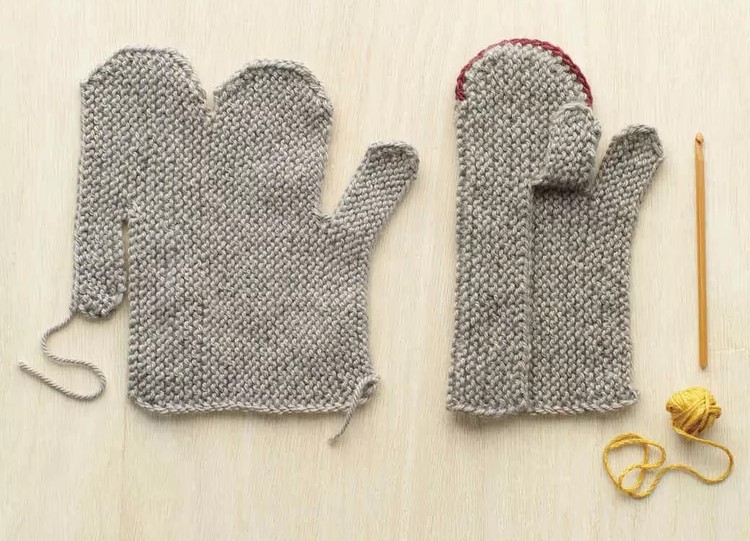
You’re reading through the instructions, but you realize you want to make the thumb longer. And also, you want to knit the cuff after finishing the body of the mitten because you want to use a fancy directional design. Basically, you want to make some changes to the fabrication plan. How can you make these edits and get a new knitting pattern?

Has this ever happened to you?
Can we turn to computation? Lots of existing work1234567 compiles some kind of shape specification to a fabrication plan. The thing we noticed, however, is that these tools provide only one or a few fabrication plans, which is entirely determined by the geometry of the input and sometimes a user-supplied thing called a “time-vector field” and a few sliders. So, if I gave you this specification of a mitten, you’d really only be able to knit it in the round from the bottom-up or top-down, or starting at some point like the end of the thumb and progressing outward.
That does not encompass my original knitting plan, which is knit flat rather than in the round, nor my new desired knitting plan, which includes knitting the cuff after the rest of the body.
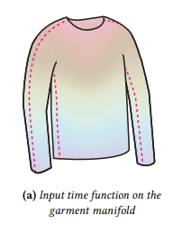
Example taken from Knit Sketching (Kaspar et al), showing a default time vector field
So how would I even go about representing my downloaded pattern as input to a knitting compiler? Maybe a small subset of math experts could painstakingly define their own time-vector fields, but otherwise we can’t get any computational help.
Even given a starting fabrication plan, there isn’t really an easy nor ergonomic way to explore different plans. As plans get more complicated, they require you to manually compute new shapes, keep track of fabrication steps, and avoid violating constraints. What would you do if you wanted to knit part of it in the round, or add colour or texture detail to sub-components, or break the design apart into much smaller pieces?
The fabrication plan is what records details like these, which is why we believe that the design of a sock, or a mitten, or anything else depends directly on the fabrication plan, and not just the shape: if we wanted, we could make socks from vertical stripes of knitting, or wrapped ribbons, or by leaving the heel until later – producing distinctly different designs.
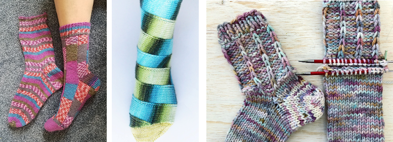 [Left] General Hogbuffer Stripe Tease by MiaMidori,
[Middle] Louise Robert Carousel sock,
[Right] Afterthought heel
[Left] General Hogbuffer Stripe Tease by MiaMidori,
[Middle] Louise Robert Carousel sock,
[Right] Afterthought heel
Each of these designs represents a totally different way to make a sock, a way that craft knitters have imagined and desired, and yet none of these patterns are well-supported by existing software.
What can we do to specify fabrication plans and integrate them into our knitting compilers? In other words, how can we expand the space of programs we can actually compile to?
I’ve been thinking a lot about this problem. My solution is couched in a couple basic principles.
- We need some way to codify fabrication plans as standalone objects, rather than implicitly attaching them to the shape. A way to do that simply is as a text format, which is easily distributed, ingested, and can even be manually understood without too much headache.
- 3D representations offer too many degrees of freedom, especially when most objects are actually composed of simple panels that are connected together. To that end, I propose a 2D-only representation, where SVG shapes are used as inputs, and the user can specify how to assemble or disassemble them. 2D shapes are also great because algorithms over 3D shapes can be brittle, especially considering knittability assumptions.
Important design tasks are poorly supported in previous systems: representing the myriad ways knit objects are made, allowing independent changes to the shape or the fabrication method, and encouraging exploration of fabrication plans without painstaking manual editing. Our system will enable them.
For example, if we wanted to design a mitten, we could start with this outline that shows the basic shape of the mitten. We create two of the same panel, and join them together at the sides.
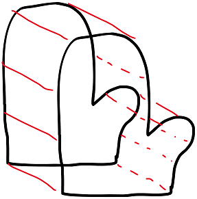
Now, we can play with this shape. We can cut things up and put them back together in different ways to produce all these different fabrication plans.
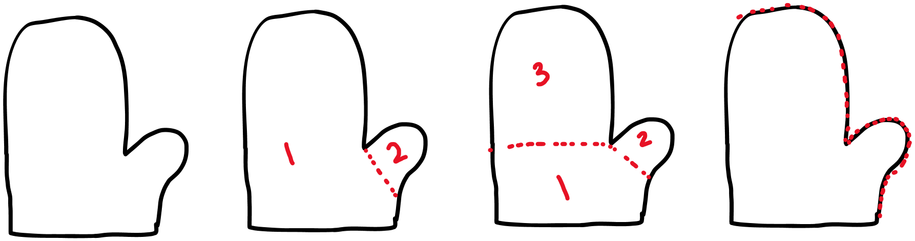 (left) knit top to bottom, (left middle) knit the body first and thumb second, (right middle) further separate the palm, thumb, and fingers, (right) knit flat and sew along dotted line
In this blog post, we’ll break down part of the pipeline we’re writing to make this vision of a new, 2D fabrication plan compiler a reality. In particular, we’ll talk a little about how to compile an SVG shape into a specification for a knitted object, especially when there might be additional knitting complexity.
A Simple Introduction to 2D Panels for Knitting
Knit objects are fundamentally made of loops that are pulled through other loops. This diagram is 3 loops wide and 3 loops tall, and is made of knit stitches on the bottom and purl stitches on the top:
How do humans know how to produce the correct knit objects? When you download a knitting pattern from online, it often looks like this:
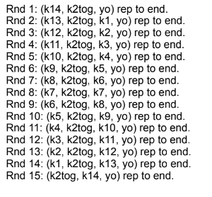
which is a series of instructions for the knitter on what new loops to make and where. So, taking our original diagram, the instructions might have looked something like this:
row 1. k3
row 2. p3
But you can imagine that if I wanted to change the width of the rectangle, I would have to make sure to update both the instructions for row 1 and row 2.
Now you might think of course, “parameterize!” So one simple solution would be to automatically derive the knitting instructions based on the shape I want. For example, I could give a width and height of a rectangle, and then generate the correct number of rows and instructions within the rows.
Additionally, if I wanted to change the width of the shape as I’m knitting, I can use an important shaping tool: increases and decreases. An increase creates a loop where there previously was none, and a decrease reduces the width from two stitches to one stitch.
So, to parameterize over more complex shapes, I could give an SVG specification, which I could then discretize into a graph of knits, purls, increases, decreases, and other stitches.
Capturing Complex Fabrication Aspects
Something that is difficult to capture with just a pure specification of the shape outline, is the fact that within a pattern, the knitting direction might change. A pattern might do this to make an interesting design feature or distribute colour in a different way.
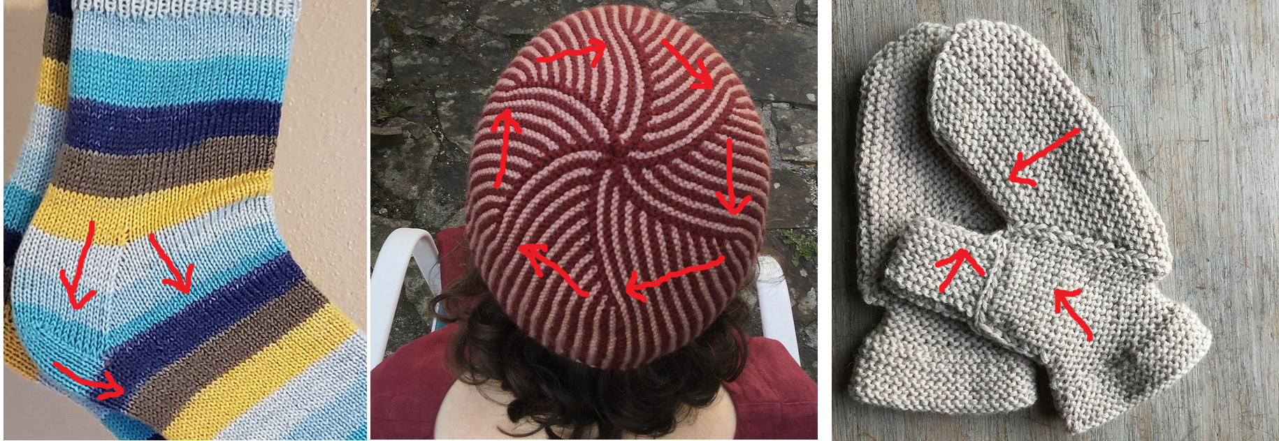 [Left] Basic Sock with Integrated Heel made by alohanoa,
[Middle] Little Venice made by thirdsetofneedles,
[Right] EZ Garter st mittens made by angharadt
[Left] Basic Sock with Integrated Heel made by alohanoa,
[Middle] Little Venice made by thirdsetofneedles,
[Right] EZ Garter st mittens made by angharadt
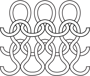
It might even be to achieve a shape that is simple to do with a direction change but difficult without one. Consider a cone net:
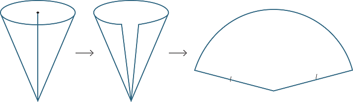
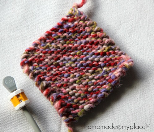
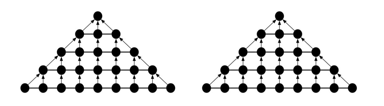
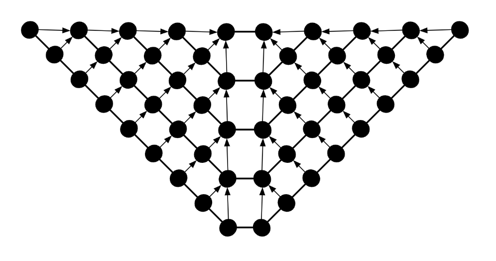
If we wanted to knit the shape of the net, we could do so by starting from a single stitch (such as the leftmost outer point or the centre point) and increasing and decreasing aggressively at the boundaries to change the width but keeping the middle flat. I’ll illustrate this with a diamond rather than a cone, which has a similar shape of widening and narrowing. Observe how the lines of bumps stay parallel throughout the object.
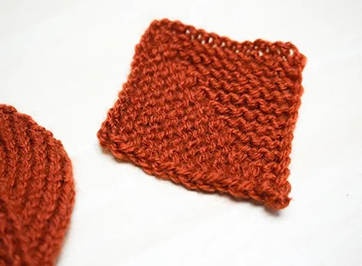
Or we could basically knit triangles side-by-side, joining them with increases and decreases placed in the middle rather than at the edges. Observe here how the lines of bumps changes directions from one half to the other – it’s no longer parallel throughout the object.
This blog post has a great comparison and also shows how the knitting direction affects the overall look.
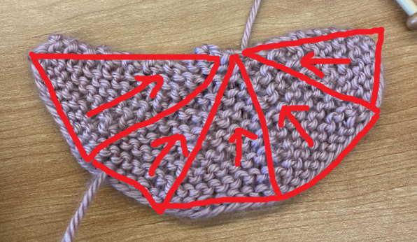
Here’s an example I knit of a full cone pattern, where you can see the lines of bumps change angles as you go from left to right:

These direction changes also do more than change the look of a flat shape – their effects vary from outright creating shapes that don’t lie flat using short rows, to simply encouraging 3D structures by using increases/decreases to create natural fold lines that don’t exist on a homogeneously-knit shape.
So, carefully placing directional changes allows you to control the 3D shape more precisely. Obviously, we need to support this type of instruction so we can fully express different fabrication plans. Specifying direction changes range from very cumbersome to impossible to do in existing compilers.
Now, how do we actually put these direction changes into our SVG specification of the outline, which is essentially just a very lightweight set of points?
One way could be to specify the line where the knitting direction changes. Or alternatively, give the knitting direction for each “point” within the SVG shape. But, you can imagine that these types of specifications involve searching within the knitgraph for the correct places to create direction changes.
We discovered a simple approach that doesn’t require us to search within knitgraphs and edit them at all. First, note the way that the direction changes create intuitive sub-shapes within a flat knit panel.
Our observation is that direction changes occur naturally when we first create knitgraphs for these sub-shapes, and then merge them together. Essentially, the direction change is caused by a series of increases and decreases placed between sub-shapes. If we were to knit each sub-shape on its own, it would already have decreases along the edges. So, if we just join these sub-shapes while knitting, the direction change happens for free.
That is to say, the direction change is the byproduct of merging these sub-shapes!
Now that I’ve told you about the basic idea behind enabling direction changes, Marlena will walk us through the high-level of how this happens in our tool!
Low-Level Cone Example
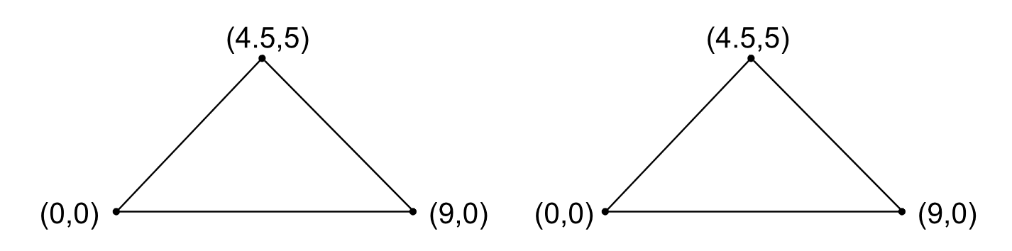
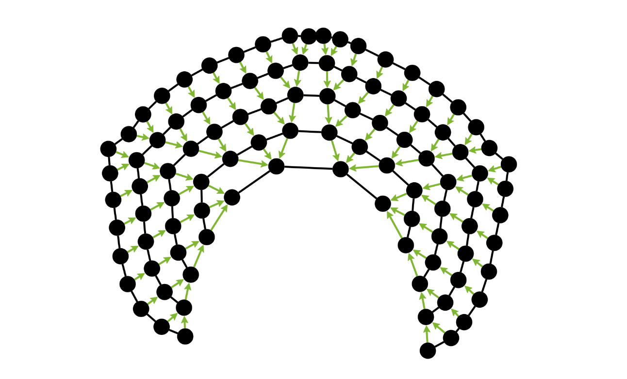
Let’s walk through what it looks like to represent two sub-shapes of the cone net above. We’re going to create two triangles and connect them along their side edges.
We begin by defining two SVG triangles. These shapes outline two panels of the cone. We derive knitgraphs in the shape of the outlines in order to merge and manipulate knitting direction.
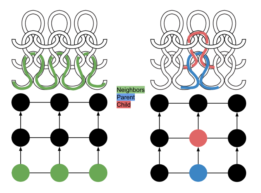
Each knitgraph represents a panel of knitting with the shape of its SVG counterpart. A knitgraph, similar to a physical piece of knitting, is composed of connected loops. Neighbor loops are knit sequentially on the same segment of yarn, and child loops are pulled through their parents. Our knitgraph diagram represents loops as circles, neighbor relationships as horizontal lines, and parent/child relationships as arrows pointing from parent to child. The knitting direction represents to the order that stitches are knit, where parents come before children. Each knitgraph has a unique ID, which loops store. This identifier maintains organization once single knitgraphs are merged together into compound knitgraphs.
Knitgraphs are useful because they are characteristic of real-world knit objects. However, they are not user-friendly to interact with. Interaction usually involves manipulation of specific loops which can be difficult to identify among the numerous loops that compose a knitgraph. To prevent users from handling knitgraphs directly, we establish a link between loops and the location they correspond to on the SVG. Thus, users specify a location on the SVG and are returned the loops at that location on the knitgraph. Compound knitgraphs are linked to several SVGs which are distinguishable by the unique IDs of the knitgraphs they are individually linked with.
The next step in our cone construction is to merge the triangle knitgraphs on edges that contain loop decreases. In other words, we will join the knitgraphs by creating neighbor relationships between their loops. We first choose one triangle knitgraph to be oriented on the left side of the merge and the other to be on the right. Let’s refer to these as leftTriangle and rightTriangle. Then we identify the edges on the SVGs that correspond to the knitgraph edges we want to merge on. This will be (9, 0) -> (4.5, 5) on the leftTriangle and (0, 0) -> (4.5, 5) on rightTriangle. A verification process ensures that these edges correspond to an equal number of loops on the rightmost edge of leftTriangle and leftmost edge of rightTriangle.
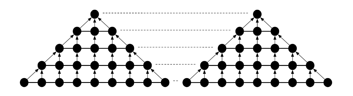
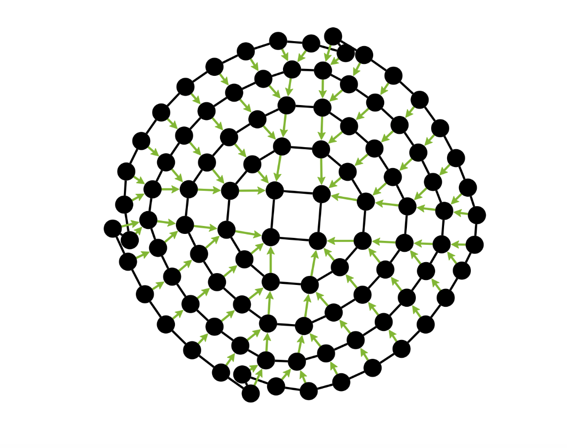
At this point we know which loops should facilitate the merge and we can assign neighbor relationships to the loops that are aligned next to each other. The result is a compound knitgraph with a knitting direction change. (Note that as a consequence, in our system, we know that non-compound knitgraphs never contain direction changes.)
We complete our cone by repeating this process on the compound knitgraph with a couple more triangle knitgraphs. There will still be one open edge that the user can sew up to complete the closed cone shape.
Conclusion
Merges belong to a larger collection of operators over knitgraphs that we have designed to support expressivity and knittability in the 2D system:
- Gauge: SVGs are unitless – when they are converted into knitgraphs, a user-defined discretization takes place that determines how many loops a specific distance in an SVG corresponds to. If it is too few, detail can be lost from the intended design. We provide gauge operations to identify and report these effects.
- Merges: Merging operations allow for simplified manipulation of knitting direction and texture. Merges can achieve short rows in addition to increase/decrease patterns. Short row merges involve manipulation of parent/child loop relationships rather than neighbor relationships.
- Tubing: Tubing operations facilitate knitting in the round – a technique that the 2D approach would otherwise disallow but is necessary to provide users with a full range of expressiveness.
- Chunking: Chunking operations verify knittability. There exist real-world constraints over what kinds of patterns can be knit in one contiguous piece. By applying these constraints to knitgraphs, we can recognize when a piece is not knittable and split it into knittable chunks. These chunks are knit separately and seamed together to reconstruct the original design.
Those operations cover pretty much everything we need to do in the land of manipulating knitgraphs, but the system is far from complete. We have the ability to take a complete SVG specification with information about knitting direction, texture, etc. and create a corresponding knitted shape.
But how did we generate that SVG in the first place? How do we support the exploration of different shapes from an initial specification, and write that down so we can disseminate the format later? All of this is supported by a reference-aware scheduling language that begins with a basic specification of flat panels; we then write programs over them using scheduling operators that we define, such as cut, sew, and merge. The program can be interpreted (and re-interpreted for different starting shapes) into transformed SVG shapes and then knitgraphs. We then compile knitgraphs into knitting instructions, completing the pipeline. Finally, there will need to be work making a user interface that supports a natural shape-editing and clicking interaction.
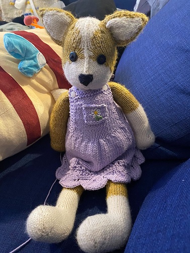
Once we have those pieces in place, we’ll have a new compiler and knitting design system for users to easily create, modify, and explore new and existing knitting patterns across a vast, previously unsupported design space. All those tasks that we found hopeless at the beginning of this blog post will be enabled by our techniques! I think the first thing I’ll use it for is to make some cute clothes for my knitted corgi eventually. Maybe some booties? Let us know what you think!
Acknowledgements. Thanks to our collaborators Maaz Ahmad and Mackenzie Leake, as well as our advisors, Zachary Tatlock and Adriana Schulz, for all their input on this project!
-
Vidya Narayanan, Kui Wu, Cem Yuksel, and James McCann. 2019. Visual knitting machine programming. ACM Trans. Graph. 38, 4, Article 63 (August 2019), 13 pages. https://doi.org/10.1145/3306346.3322995 ↩
-
James McCann, Lea Albaugh, Vidya Narayanan, April Grow, Wojciech Matusik, Jennifer Mankoff, and Jessica Hodgins. 2016. A compiler for 3D machine knitting. ACM Trans. Graph. 35, 4, Article 49 (July 2016), 11 pages. https://doi.org/10.1145/2897824.2925940 ↩
-
Vidya Narayanan, Kui Wu, Cem Yuksel, and James McCann. 2019. Visual knitting machine programming. ACM Trans. Graph. 38, 4, Article 63 (August 2019), 13 pages. https://doi.org/10.1145/3306346.3322995 ↩
-
Vidya Narayanan, Kui Wu, Cem Yuksel, and James McCann. 2019. Visual knitting machine programming. ACM Trans. Graph. 38, 4, Article 63 (August 2019), 13 pages. https://doi.org/10.1145/3306346.3322995 ↩
-
Kui Wu, Hannah Swan, and Cem Yuksel. 2019. Knittable Stitch Meshes. ACM Trans. Graph. 38, 1, Article 10 (February 2019), 13 pages. https://doi.org/10.1145/3292481 ↩
-
Benjamin Jones, Yuxuan Mei, Haisen Zhao, Taylor Gotfrid, Jennifer Mankoff, and Adriana Schulz. 2021. Computational Design of Knit Templates. ACM Trans. Graph. 41, 2, Article 16 (April 2022), 16 pages. https://doi.org/10.1145/3488006 ↩
-
Georges Nader, Yu Han Quek, Pei Zhi Chia, Oliver Weeger, and Sai-Kit Yeung. 2021. KnitKit: a flexible system for machine knitting of customizable textiles. ACM Trans. Graph. 40, 4, Article 64 (August 2021), 16 pages. https://doi.org/10.1145/3450626.3459790 ↩