Verilog Programs are Pure Expressions
module counter(input clk, output [7:0] out);

  wire [7:0] plusone_out, register_out;

  register register_instance(
    .in(plusone_out), .out(register_out), .clk(clk));
  plusone plusone_instance(
    .in(register_out), .out(plusone_out));

endmodule
Abstract. Verilog is a language of fundamental importance. Yet, despite that fact, it is mostly ignored in the world of programming languages (PL) and compilers research. In this post, I present one very simple fact about Verilog programs: they represent pure expressions. In explaining this, I hope to make Verilog more approachable by a programming languages and compilers audience.
Goals of this post. The direct goal of this post is to explain the syntax and program structure of a simple subset of Verilog—specifically, structural Verilog—to those with a PL/compilers background. Concretely, the reader will be able to understand Verilog code like the code shown at the top of this post. The indirect goal is to build confidence and inspire curiosity within PL/compilers researchers towards hardware topics, by showing a more PL-flavored aspect of Verilog, a foundational piece of hardware tooling.
Non-goals of this post.
This post
is not a general
introduction
to Verilog.
I
will not explain
many of the most basic features
of Verilog, e.g.
how always blocks work, or
the difference between wire and reg.
What’s the most important language in the world? Maybe you’d say JavaScript—it runs the vast majority of the web, after all. Or maybe C++, as it underlies the world’s most important systems. Or perhaps Rust, or Haskell, or Python, or any number of other languages. Whatever language you might tell me is most important, I’d bet one thing is true: that language runs on hardware, be it your phone, a GPU, or a server in the cloud. Furthermore, it’s a safe bet that all of that hardware was designed with a common language: Verilog. Whether or not Verilog is the most important language in the world is up for debate—but, without a doubt, it is a language of fundamental importance.
Verilog is becoming more and more important because understanding hardware is becoming more and more important. The goal of most computer scientists—architects, operating systems designers, programming language and compiler engineers, and beyond—has long been to provide abstractions which hide details of the hardware–software stack from application developers. However, as we push the limits of computing in all directions, those abstractions may hinder as much as help. Extracting maximum performance from a processor when building a compiler, for example, requires intimate knowledge of the microarchitecture. High-performance applications like machine learning have even required fully custom hardware to achieve mainstream utility. And it isn’t just performance that requires hardware knowledge: security researchers also need to deeply understand hardware details, given the rise of side-channel attacks.
However, despite its fundamental importance, Verilog has been of little interest to the programming languages/compilers research communities. A search for “Verilog programming language” on Google Scholar returns about 36k results. Meanwhile, “Rust programming language” returns 42k results, “C++ programming language” returns 52k results, “JavaScript programming language” returns 339k results, and “Python programming language” returns 435k results. (Note that you see a similar ranking for queries of the form “<language> PLDI”, as well.) This lack of interest is a loss for both sides.
The goal of this blog post is to make Verilog less intimidating and more interesting to those with a programming languages or compilers background. My hope is that our community of programming languages and compilers researchers will pay more attention to this fundamentally important language—this post is just one small attempt towards that end.
Put simply: programming languages and compilers folks shouldn’t be intimidated by Verilog, because Verilog programs capture things that our community is very familiar with: pure expressions. However, they do so in a unique way, via the use of cyclic graphs.
(Note: in this post, I am referring to just a subset of Verilog, called structural Verilog. Verilog is a complicated language, and contains within it many coexisting sub-languages, which capture different levels of abstraction. All Verilog destined to become hardware (as opposed to Verilog written purely for simulation) is eventually converted into structural Verilog, and thus structural Verilog is a good starting place.)
Let’s begin by discussing some examples of pure expressions and the underlying program structures they capture.
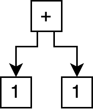
The simplest program structures are trees, often referred to as abstract syntax trees or ASTs. For example, the following expression (in LISP-like s-expression syntax):
(+ 1 1)
Captures the following tree program structure:
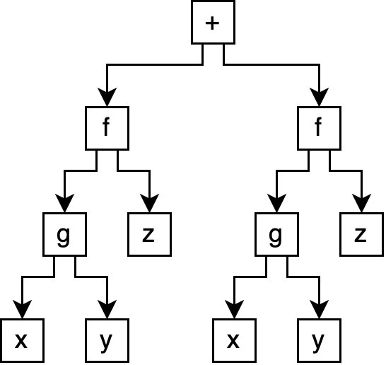
However, imagine our program was a bit more complex:
(+ (f (g x y) z) (f (g x y) z))
This produces a tree with significant duplication:
In this case, we might want
a representation
that allows for sharing,
so that we don’t need to
capture
the (f (g x y) z) expression
twice.
This not only makes the program
representation smaller,
but can be essential
for expressing optimizations
during compilation.
A common way to capture sharing
is via the use of
let bindings:
(let ([expr (f (g x y) z)])
   (+ expr expr))
This expression first binds
the (f (g x y) z) expression
to a name, expr,
and then uses that name twice
in the + call.
Now, our
program structure
is no longer a tree,
and is instead
a graph:
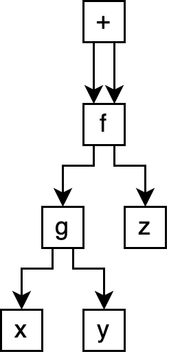
Specifically, an acyclic graph. These structures, unsurprisingly, are generally referred to as directed acyclic graphs, or DAGs. DAGs are very commonly used to capture program structure, as they are expressive enough to allow for sharing, while also preventing the complexity induced by graph cycles.
However, this begs the question: are there any uses for cyclic graphs when capturing programs? Perhaps unsurprisingly given the topic of this post, it turns out that cyclic graphs are especially useful in representing hardware designs.
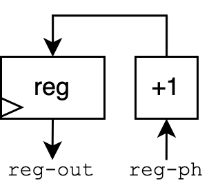
Let’s consider a simple circuit. Don’t worry if you have no hardware background—I will explain.
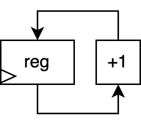
This is a schematic for a very simple counter circuit, represented as a directed, cyclic graph. Assume the “+1” block is a hardware circuit which simply increments its input. The block labeled “reg” is a register: a fundamental unit in hardware which saves its input at every timestep (overwriting the value from the previous timestep). Timesteps in hardware are captured by a clock, an electrical signal that regularly alternates between 0 and 1 to keep the circuit synchronized. A triangular-shaped port on a register is the traditional way to indicate a clock input.
This counter circuit’s behavior is very simple. The current value stored in the register is passed into the +1 block, whose output is then fed back into the register. Each timestep, the register saves the newly incremented value. Thus, the output of the circuit can be viewed as a stream over all time:
| timestep | 0 | 1 | 2 | … |
|---|---|---|---|---|
reg output |
0 | 1 | 2 | … |
As we saw in the image above, capturing this circuit using a cyclic graph was very natural. But how would we write down this circuit as an expression? For both our AST and DAG examples, the conversion to and from expressions is straightforward. However, with our cyclic graph, capturing the graph in text is not as straightforward. That is, drawing circuit diagrams with cycles is fairly straightforward. However, developing a text-based representation is not as straightforward! Spoiler: this task is exactly what structural Verilog solves. However, before we discuss Verilog’s solution, let’s make an attempt at our own.
Assume we want the output of the register
to be the topmost expression.
So we can start with a reg expression:
(reg ...)
The input to the reg is the output
of our +1 block, so we can
insert a +1 expression:
(reg (+1 ...))
But now, what do we fill in
for that ...?
What we want
is the same reg again,
somehow:
(reg (+1 (reg ...)))
Which we can see will just lead to an infinitely looping expression.
What is the root of our problem?
Well,
when initially defining
our reg expression,
we seem to need a way
to refer to the reg
expression we’re in the process
of defining!
So, much like we introduced
the let expression
to introduce sharing,
we can also introduce
a placeholder construct
to allow us to refer to an expression
before it’s defined:
(let ([reg-ph (placeholder)]
      [reg-out (reg (+1 reg-ph))])
   (connect reg-ph reg-out)
   reg-out)
Let’s step through this. The first two lines generate a partial circuit:
(let ([reg-ph (placeholder)]
      [reg-out (reg (+1 reg-ph))])
   ...
We use a placeholder to give us
an input we can use to +1,
without it being defined.
This produces the following partial
circuit:
Then, all we need to do is connect the placeholder to the register output:
   ...
   (connect reg-ph reg-out)
   ...
This simply asserts that these two names in fact refer to the same thing—very similar to simply connecting two wires in a circuit together. This connection produces our final circuit:
Thus, we’ve seen
one example
of how to capture
cyclic expressions
in a text-based format.
But what does this have to do
with Verilog?
Well, it turns out
that a fundamental component
of Verilog—namely
Verilog wire objects—simply
serve the same role
as our placeholder
above!
Consider the following Verilog module, which is the implementation of our counter:
module counter(input clk, output [7:0] out);

  wire [7:0] plusone_out, register_out;

  register register_instance(
    .in(plusone_out), .out(register_out), .clk(clk));
  plusone plusone_instance(
    .in(register_out), .out(plusone_out));

endmodule
First, let’s discuss the syntax
at a high level.
The module and endmodule pair
wrap a module definition—not
dissimilar to a function definition
in software languages
(though with some fundamental differences
which we won’t discuss).
Within the parentheses after the module name counter
is the input and output port list,
similar to function inputs and outputs.
By default, every signal in Verilog is one bit;
brackets like [7:0] indicate a multi-bit signal.
[7:0], for example, indicates that a signal is 8 bits,
whose bits are labeled 7 (most significant) down to 0 (least significant).
The wire declarations simply declare signals used within the module.
Finally, the register and plusone lines
instantiate module instances.
Module instances are similar to function calls,
except that they aren’t just called once—instead,
a module instantiation is a piece of hardware
that is present for all time.
That is, our “plus one” module does not disappear
after the first timestep—it remains present,
producing an output each timestep.
Note that we do not show the definitions
of the register and plusone modules,
but assume they implement the “reg” and “+1”
blocks we used above.
When instantiating a module,
module input and output ports are connected
to signals
using the .<port-name>(<signal>) syntax.
So how does this Verilog example parallel our text format? First, recall how we captured the design:
(let ([reg-ph (placeholder)]
      [reg-out (reg (+1 reg-ph))])
   (connect reg-ph reg-out)
   reg-out)
Now, look at the Verilog. There are two parallels to point out.
First: Verilog wires are placeholders.
Note that
we pre-declare
the plusone_out and register_out
wires.
These wires are serving
the exact same role
as reg-ph did for us above:
they give us names
that we can
refer to
as we instantiate our
plusone
and register module instances.
Second: Verilog port connection is the same as our connect.
Our connect expression
is implemented by Verilog’s
module instantiation mechanism.
For example,
by setting plusone_out as the
in port of the register
and the out port of the
plusone module, we effectively
assert the equality
of these two expressions
in the graph.
Thus, though Verilog looks far different from the toy text format we developed in this post, both text formats convey the same thing: they capture directed, cyclic circuits as pure expressions. It is my hope that this example hints at the interesting programming languages and compilers ideas and challenges hiding inside Verilog.
Again, this post is meant
to explain a single very simple fact
about the simplest subset of Verilog:
structural Verilog.
Moving forward from here,
I suggest beginning to learn about
behavioral Verilog:
the higher-level subset of Verilog
which is more commonly written
by hardware designers.
Specific topics to look into
include
the implementation of basic circuit elements
such as registers
and combinational logic
using always blocks.
Gus Smith is a 6th-year PhD student in the PLSE lab. His website is located at https://justg.us.